Finite State Machines (FSM)
With latches/flip-flops and registers/register files, we have the building blocks to store state. The next question is: how does state evolve over time, and how does a circuit make decisions based on input and current state?
A finite state machine (FSM) is a standard abstraction for such sequential systems. Compared with a register file (data storage), an FSM focuses on control and flow: it uses a finite set of states to represent the system’s phase, and transitions between states under a clock.
Hardware decomposition:
- State register (flip-flops) storing current state
- Combinational logic computing next state and outputs based on and inputs
Core behavior:
Outputs:
A Moore FSM output depends only on state; a Mealy FSM output depends on both state and input.
Experiment: Sequence detector (pattern 101)
Section titled “Experiment: Sequence detector (pattern 101)”Objectives
Section titled “Objectives”- Understand how to model an FSM.
- Write a Mealy FSM state diagram and state transition/output table.
- Implement and verify a sequence detector in Logisim Evolution.
Environment
Section titled “Environment”- Simulator: Logisim Evolution
Principles
Section titled “Principles”Input is a 1-bit serial signal . Output when the most recent three inputs form exactly 101; otherwise .
We use a Mealy structure so can assert immediately when the last bit is received.
Task 1: State abstraction and state diagram
Section titled “Task 1: State abstraction and state diagram”Define three states based on matched prefix:
- : no match (no valid prefix)
- : matched “1”
- : matched “10”
Draw the state transition diagram.
Task 2: State encoding and state transition/output table
Section titled “Task 2: State encoding and state transition/output table”Encode the 3 states using 2 bits , for example:
State 11 is unused; for robustness, force it to transition unconditionally back to .
Complete the state transition/output table below.
| 0 | 0 | 0 | |||
| 0 | 0 | 1 | |||
| 0 | 1 | 0 | |||
| 0 | 1 | 1 | |||
| 1 | 0 | 0 | |||
| 1 | 0 | 1 | |||
| 1 | 1 | 0 | |||
| 1 | 1 | 1 |
Table 3.1: State transition and output table for a 101 sequence detector.
Task 3: Derive logic equations and build the circuit
Section titled “Task 3: Derive logic equations and build the circuit”Use D flip-flops for the state register:
Derive boolean expressions for , , and based on Table 3.1, then implement the circuit in Logisim Evolution.
Task 4: Verification
Section titled “Task 4: Verification”Manually set and toggle the clock to generate rising edges. Verify with sequences such as:
- : should be 1 on the third tick.
- : should assert twice.
- : is 1 only on the tick that completes “101”.
Results
Section titled “Results”- State diagram, completed Table 3.1, and expressions for , , and .
- Circuit screenshot (2 D flip-flops + combinational logic).
- Test record for at least 3 input sequences with per-tick state and output .
Question
Section titled “Question”Why is it recommended to force unused state 11 back to the initial state instead of transitioning arbitrarily? How does this relate to reliability?
Experiment: 3-digit decimal counter (000 → 999)
Section titled “Experiment: 3-digit decimal counter (000 → 999)”A counter is a classic sequential module: state registers that evolve under a clock. This experiment asks you to design a 3-digit decimal counter and display it using three 7-segment displays, counting from 000 up to 999 in a loop. The counter should also stop automatically when a specified stop condition is met.
Objectives
Section titled “Objectives”- Understand 7-segment encoding and implement digit-to-segment decoding.
- Learn to decompose a complex circuit into reusable modules (counting cell, carry logic, display decoding, etc.).
Environment
Section titled “Environment”- Simulator: Logisim Evolution
Principles
Section titled “Principles”1) Structure
Section titled “1) Structure”Treat the counter as three cascaded decimal digits: ones, tens, hundreds.
- ones increments every clock
- ones rolling 9→0 produces a carry to tens
- tens rolling 9→0 produces a carry to hundreds
- 999 rolls back to 000
This can be designed using an FSM mindset where each digit is a FSM.
2) 7-segment display
Section titled “2) 7-segment display”A 7-segment display uses 7 LEDs to form digits. Logisim Evolution’s display is shown in Figure 3.8.
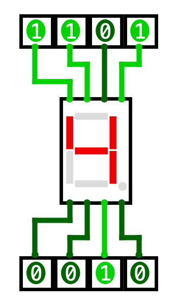
Figure 3.8: Example 7-segment display showing the digit 4.
Inputs and outputs
Section titled “Inputs and outputs”Inputs:
- : clock
- : reset (after reset, the value should be 000)
- : count enable ( counts; holds)
Outputs:
- Three 7-segment displays showing hundreds/tens/ones digits.
-
Base functionality (000 → 999 loop)
- When , increment by 1 on each clock edge.
- Sequence: 000, 001, 002, …, 998, 999, 000, …
- Display all three digits on three 7-seg displays.
-
Stop functionality (stop at )
- Choose a two-digit decimal number (00–99), e.g., last two digits of your student ID or day-of-month.
- Stop threshold is (i.e., a number between 500 and 599).
- When the counter reaches that value, it should stop (hold display) until reset or re-enabled.
- Explain your chosen resume behavior in your report.
Design hints
Section titled “Design hints”- Encapsulate a single decimal-digit counting unit as a subcircuit and reuse it for tens/hundreds.
- Carry signals are the key to cascading digits.
Results
Section titled “Results”- Top-level circuit screenshot showing:
- three digit counters, three 7-seg displays
- the stop-control path
- Subcircuit interface documentation (inputs/outputs and meanings).