Polling I/O
With MMIO, a device appears as registers in the address space. The simplest way to use such a device is polling: repeatedly read a status register until the device is ready, then perform the data read/write.
Pros:
- very simple hardware/software model
Cons:
- wastes CPU cycles spinning while waiting
This lab uses Logisim Evolution’s SoC component and its JTAG UART device.
JTAG UART register map
Section titled “JTAG UART register map”| Offset | Register | R/W | Description |
|---|---|---|---|
| +0 | Data | R/W | data register (send/receive) |
| +4 | Control | R/W | status + interrupt control |
Table 9.1: JTAG UART MMIO register map.
Data register
Section titled “Data register”| Bits | Name | Attr | Meaning |
|---|---|---|---|
| [7:0] | DATA | R/W | write: push ASCII byte to TX FIFO (ignored if full). read: pop a byte from RX FIFO (0 if empty, VALID=0). |
| [15] | VALID | R | 1 if read successfully popped a byte; 0 if RX FIFO empty |
| [31:16] | RAVAIL | R | remaining RX FIFO count after pop (0 if empty) |
Table 9.2: JTAG UART Data register fields.
Control register
Section titled “Control register”| Bits | Name | Attr | Meaning |
|---|---|---|---|
| [0] | RE | R/W | read interrupt enable |
| [1] | WE | R/W | write interrupt enable |
| [8] | RIP | R | read interrupt pending (when RE=1 and condition holds) |
| [9] | WIP | R | write interrupt pending (when WE=1 and condition holds) |
| [31:16] | WSPACE | R | free space in TX FIFO |
Table 9.3: JTAG UART Control register fields.
Experiment: Polling-based I/O
Section titled “Experiment: Polling-based I/O”Objectives
Section titled “Objectives”- Understand MMIO access.
- Use polling to access a device safely.
- Build and run a minimal bare-metal I/O program in C.
Environment
Section titled “Environment”- Simulator: Logisim Evolution
- Toolchain:
riscv64-unknown-elf-gcc
Task 1: Polling output
Section titled “Task 1: Polling output”Build the SoC wiring (see Figure 9.2).
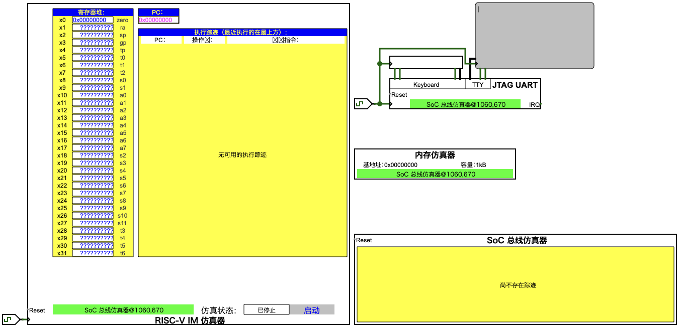
Figure 9.2: JTAG UART SoC wiring.
Fill in JTAG_UART_BASE, uart_can_write(), and uart_can_read():
#include <stdint.h>
#define JTAG_UART_BASE 0x????????u
#define UART_DATA (*(volatile uint32_t *)(JTAG_UART_BASE + 0u))#define UART_CTRL (*(volatile uint32_t *)(JTAG_UART_BASE + 4u))
static inline int uart_can_write(void) {  /* TODO: return 1 if TX FIFO has space, else 0 */  return 0;}
static inline int uart_can_read(uint32_t v) {  /* TODO: v is UART_DATA; return 1 if it contains a valid input byte */  (void)v;  return 0;}
static void uart_putc(uint8_t ch) {  while (!uart_can_write()) { }  UART_DATA = (uint32_t)ch;}
static uint8_t uart_getc(void) {  uint32_t v;  do {    v = UART_DATA;  } while (!uart_can_read(v));  return (uint8_t)(v & 0xFFu);}
static void uart_puts(const char *s) {  while (*s) uart_putc((uint8_t)*s++);}
int main(void) {  uart_puts("Hello, JTAG UART!\n");  for (;;) { }}
Code 9.1: Polling-based UART output skeleton (uart_poll.c).
Linker script (place code at 0x0):
ENTRY(main)
SECTIONS{  . = 0x00000000;  .text   : { *(.text*) }  .rodata : { *(.rodata*) }  .data   : { *(.data*) }  .bss    : { *(.bss*) *(COMMON) }}
Code 9.2: Minimal linker script (link.ld).
Build:
riscv64-unknown-elf-gcc -march=rv32i -mabi=ilp32 \ -ffreestanding -nostdlib -nostartfiles \ -Wl,-T,link.ld \ -O2 -o uart_poll.elf uart_poll.cTask 2: Keyboard echo
Section titled “Task 2: Keyboard echo”Replace the infinite loop with:
for (;;) { uint8_t ch = uart_getc(); uart_putc(ch);}Results
Section titled “Results”- C source for both tasks.
- Screenshot of terminal output/echo.
Questions
Section titled “Questions”- Why must polling output wait for TX space? What happens if you ignore it?
- Why must input polling check “new data valid” before using the byte?
- What is the CPU utilization drawback of polling?