Control Unit Design
After the datapath is built, the next step is designing the control unit. In a single-cycle CPU, the control unit is combinational logic that reads the current instruction fields and produces control signals within the same cycle.
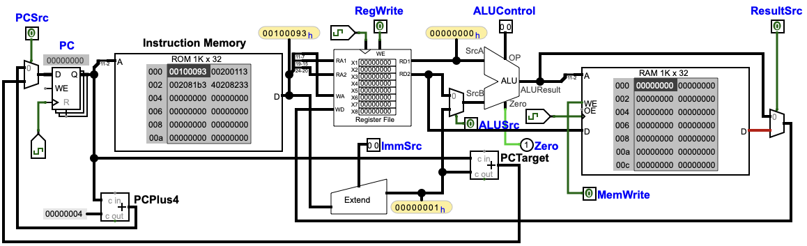
Figure 5.5: Reference datapath diagram.
Key control signals (for our minimal ISA subset):
RegWrite: register file write enableImmSrc: immediate type selection (I / S / B)ALUSrc: ALU operand B source (0 = reg, 1 = imm)MemWrite: data memory write enableResultSrc: write-back source select (0 = ALU, 1 = RAM)ALUControl: ALU operation selectPCSrc: PC update select (0 = PC+4, 1 = branch target)
Instruction fields used:
opcode = Instr[6:0]funct3 = Instr[14:12]funct7[5] = Instr[30](critical bit for ADD vs SUB)
A common implementation splits control into two blocks:
- Main decoder: based on
opcode, outputs structural control signals and an intermediateALUOp. - ALU decoder: based on
ALUOpplusfunct3and key bits, outputsALUControl.
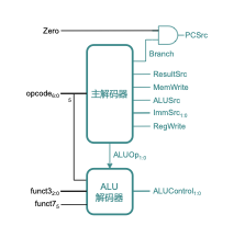
Figure 5.6: Control unit structure (main decoder + ALU decoder).
For BEQ, whether the branch is taken depends on the comparison result. Typically:
PCSrc = Branch AND Zero
Experiment: Single-cycle control unit
Section titled “Experiment: Single-cycle control unit”Objectives
Section titled “Objectives”- Understand where control signals come from and what they do.
- Learn a practical decoding design method.
- Implement a
ControlUnitsubcircuit in Logisim Evolution.
Environment
Section titled “Environment”- Simulator: Logisim Evolution
Principles
Section titled “Principles”Two-level decoding:
- main decoder:
opcode→RegWrite, ImmSrc, ALUSrc, MemWrite, ResultSrc, Branch, ALUOp - ALU decoder:
ALUOp+funct3+ key bits →ALUControl
And for BEQ:
PCSrc = Branch · Zero
Task 1: Fill the main decoder truth table
Section titled “Task 1: Fill the main decoder truth table”Encoding conventions:
ImmSrc: 00 = I, 01 = S, 10 = BALUOp: 00 = ADD, 01 = SUB (for BEQ), 10 = use funct fields
| Instr | opcode | RegWrite | ImmSrc | ALUSrc | MemWrite | ResultSrc | Branch | ALUOp |
|---|---|---|---|---|---|---|---|---|
| R-type | 0110011 | |||||||
| ADDI | 0010011 | |||||||
| LW | 0000011 | |||||||
| SW | 0100011 | |||||||
| BEQ | 1100011 |
Table 5.4: Main decoder truth table (fill in during the lab; “don’t care” can be marked as --).
Task 2: Fill the ALU decoder truth table
Section titled “Task 2: Fill the ALU decoder truth table”Inputs: ALUOp, funct3, {op5, funct7_5}. Output: ALUControl (must match your ALU encoding).
| Instr | ALUOp | funct3 | {op5, funct7_5} | ALUControl |
|---|---|---|---|---|
| LW / SW | 00 | |||
| BEQ | 01 | |||
| ADD / ADDI | 10 | |||
| SUB | 10 |
Table 5.5: ALU decoder truth table (fill in during the lab).
Task 3: Draw the ControlUnit subcircuit
Section titled “Task 3: Draw the ControlUnit subcircuit”Inputs:
Instr(32-bit)Zero
Outputs:
RegWrite, ImmSrc, ALUSrc, MemWrite, ResultSrc, PCSrc, ALUControl
Use tunnels to keep wiring clean.
Task 4: Verify the control unit
Section titled “Task 4: Verify the control unit”Inject instruction encodings and check outputs:
| Instr | Assembly | Hex encoding |
|---|---|---|
| ADD | add x3, x1, x2 | 0x002081B3 |
| SUB | sub x3, x1, x2 | 0x402081B3 |
| ADDI | addi x3, x1, 4 | 0x00408193 |
| LW | lw x3, 0(x1) | 0x0000A183 |
| SW | sw x3, 0(x1) | 0x0030A023 |
| BEQ | beq x1, x2, +8 | 0x00208463 |
Table 5.6: Test instruction encodings for control-unit verification.
Results
Section titled “Results”- Screenshot of the complete control unit.
- Verification records for the test instructions (expected vs observed control signals).
Questions
Section titled “Questions”- Why split decoding into “main decoder + ALU decoder”?
- Why can’t
PCSrcfor BEQ be decided purely by opcode? - What should you do when encountering an unsupported instruction?